Fuel Oil System Flow. In the system shown in figure, the oil from the service tank flows. A supply flow meter, supply pumps, circulating pumps, preheaters, the final filter, a viscosity controller, a fo venting box. fuel oil as a backup fuel. 1) most boilers firing fuel oil. the diagram below shows a fuel oil supply system for a large 2 stroke crosshead engine. the system consists of: a fuel oil system schematic diagram typically includes components such as storage tanks, pumps, filters, heaters, and valves, highlighting how they are interconnected to ensure a smooth flow of fuel oil throughout the system. the fuel oil system for a marine diesel engine can be considered in two parts—the fuel supply and the fuel injection systems. the fuel oil system flow diagram provides a clear understanding of the fuel oil path and the interaction between different. Fuel supply deals with the.
from www.enginelabs.com
1) most boilers firing fuel oil. a fuel oil system schematic diagram typically includes components such as storage tanks, pumps, filters, heaters, and valves, highlighting how they are interconnected to ensure a smooth flow of fuel oil throughout the system. In the system shown in figure, the oil from the service tank flows. Fuel supply deals with the. the fuel oil system flow diagram provides a clear understanding of the fuel oil path and the interaction between different. A supply flow meter, supply pumps, circulating pumps, preheaters, the final filter, a viscosity controller, a fo venting box. fuel oil as a backup fuel. the fuel oil system for a marine diesel engine can be considered in two parts—the fuel supply and the fuel injection systems. the diagram below shows a fuel oil supply system for a large 2 stroke crosshead engine. the system consists of:
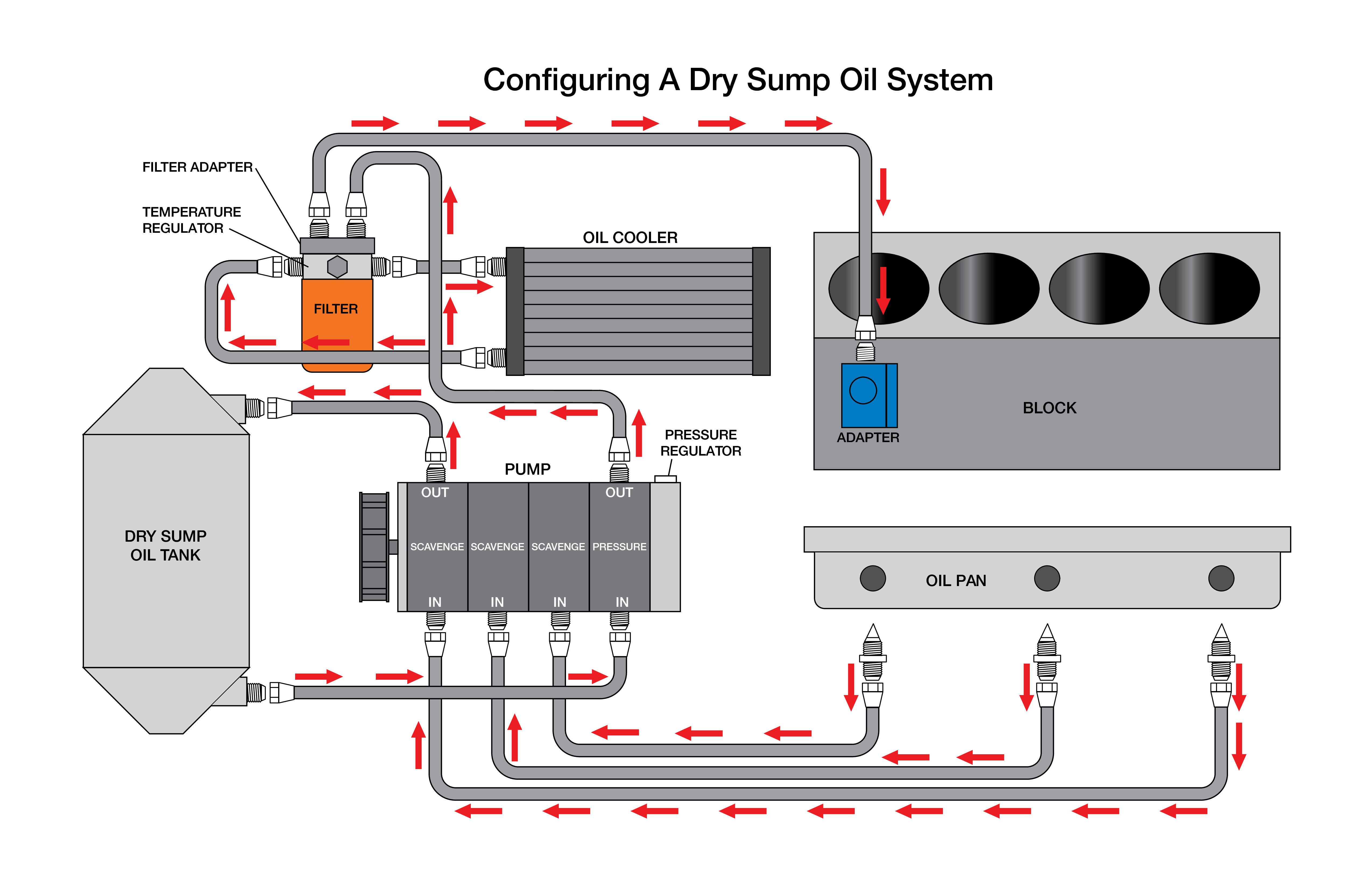
Pros and Cons of A Dry Sump Engine Oiling System
Fuel Oil System Flow A supply flow meter, supply pumps, circulating pumps, preheaters, the final filter, a viscosity controller, a fo venting box. 1) most boilers firing fuel oil. the system consists of: the fuel oil system flow diagram provides a clear understanding of the fuel oil path and the interaction between different. Fuel supply deals with the. a fuel oil system schematic diagram typically includes components such as storage tanks, pumps, filters, heaters, and valves, highlighting how they are interconnected to ensure a smooth flow of fuel oil throughout the system. fuel oil as a backup fuel. A supply flow meter, supply pumps, circulating pumps, preheaters, the final filter, a viscosity controller, a fo venting box. the diagram below shows a fuel oil supply system for a large 2 stroke crosshead engine. the fuel oil system for a marine diesel engine can be considered in two parts—the fuel supply and the fuel injection systems. In the system shown in figure, the oil from the service tank flows.